When I started this blog, I said I wasn't going to do how-tos and DIY instructions. These cars are well-loved and consequently, mods are well-documented. That said, while Supersprint MZ3 exhausts are quite popular, the actual details of their installation is not well documented. While the performance and construction quality of SS products is very, very good, the installation is very fiddly. It is not straightforward to get the tips to line up. So I thought I would fully expose and document how I did mine.
A few months ago, Turner was doing 15% off and free shipping on all SS parts. Knowing that I wanted to eventually put an SS system onto the S52 coupenut car, I bought one. Nowadays the only choice SS offers for the MZ3 is the straight-tip, non-Magnum style. At one point they did offer Magnum systems with even bigger round tips. And, at one point, they did offer DTM style with turned-up tips. Many years ago, I bought a DTM SS system for my S54.
Everything is personal preference, but I decided I wanted to move the DTM system over to the S52 and put the new straight-tipped system onto my S54. So here is how I did it. As always, feel free to do it your own way.
Years ago, Ron Stygar posted the closest thing to a how-to on SS DTM installation. It might be 75 words. His details were vague. And, he fabricated a custom hanger bracket from 304 stainless, claiming that the factory SS bracket on the aft passenger/right side was too short to get the tips level. When I installed my DTM, I agreed. And I had 4 or 5 of the custom brackets made on my side of the country. Even with a custom bracket, I probably spent 6 hours fiddling with the DTM system to get it perfect. Ron's advice was to leave the mid hanger completely loose and the connection to the mid/H-pipe fully loose too. Adjust the cans, then tighten the mid hanger and make the connection to the mid/H-pipe. My problem with his method is, while in theory it is nice, at the end of the day when the installation is complete, the exhaust is a rigid system mounted to flexible hangers and tightening one fastener will affect other joints/clearances. I prefer to connect everything and slowly tighten the whole system altogether.
 |
| Ron Stygar's bracket design on the left. Supplied SS bracket on the right. Note the bend. |
 |
| The larger bracket is needed for the aft right/passenger can hanger. |
When I got the straight tipped one, I was pleasantly surprised to see SS added a slip joint to the passenger/right can assembly. Maybe this would make installation easier. And, I noticed that instead of perfectly straight L brackets, they had supplied 4 slightly bent L brackets. Surely they know what they are doing. [I am biased
against Italian engineering because of my job... you would never catch me in a Ferrari dealer, for example, but I will try to be unbiased here]. Turns out neither of those 2 changes made it an easier install.
 |
| New straight-tip on the left. DTM on the right. Note the slip joint. |
 |
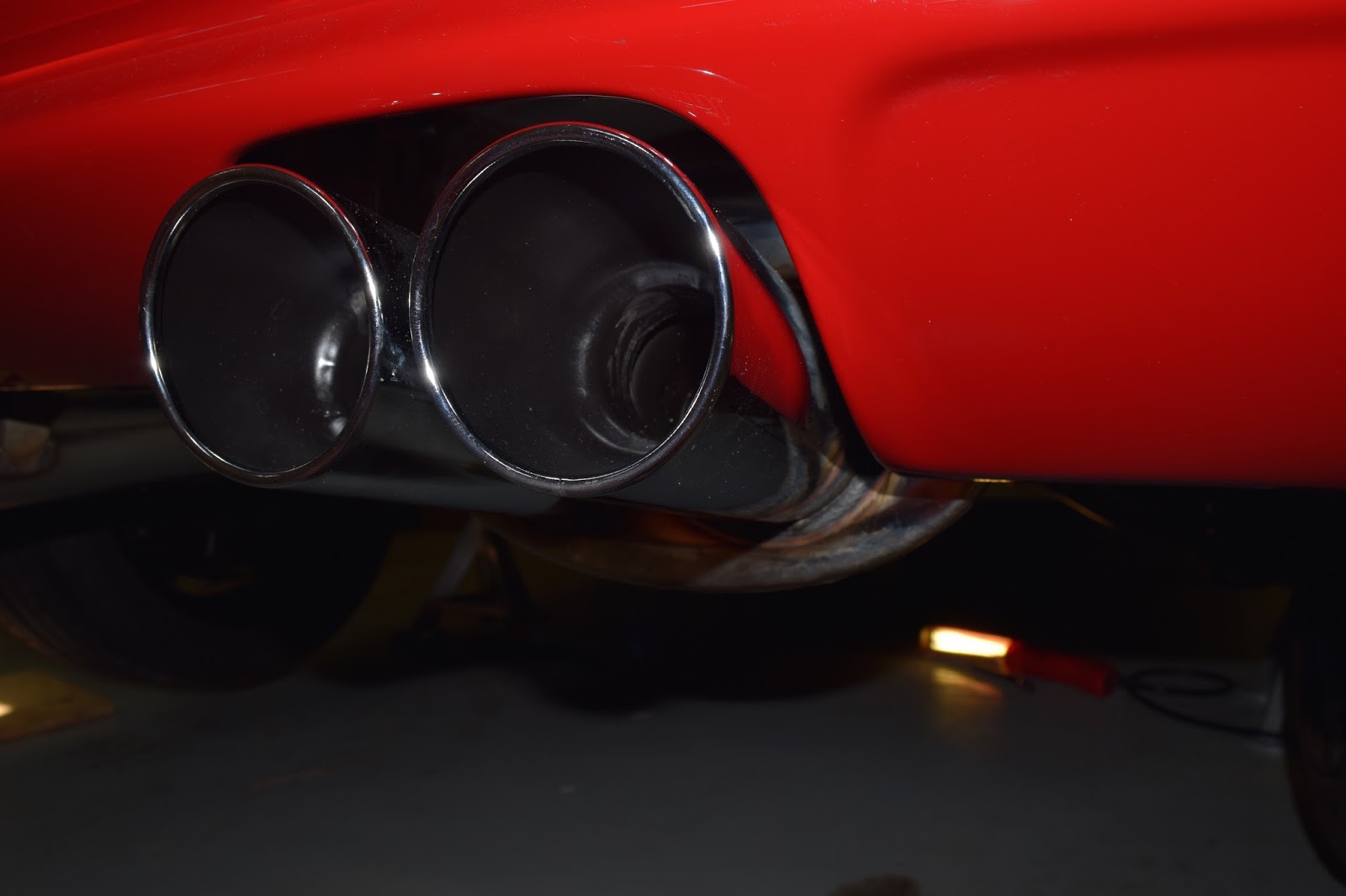
| The tips are noticeably larger on the straight-tip one. I like the look. |
 |
| DTM needs a polish before being installed on the S52 coupenut car. |
What I did.
1. Install all 4 SS brackets with bolts, nuts, and exhaust hangers snugged up (so they can slide) but not tight.
2. Install rubber donut hangers on the exhaust side. I used all new hardware and all new hangers/mounts.
3. Hang the cans and minimally attach the nuts and bolts at the mid pipe (H-pipe on S54s). Keep this connection as loose as you can for now. Do fully tighten the 13mm nuts (qty 4 per side) that hold the hangers to the body. There is no adjustment here, so it's OK to go to full tight now.
4. Set the mid supports to provide maximum ground clearance. Hopefully you can keep it that way.
5. Start on one the left/driver's side. It is the easier of the two. I used a floor jack to raise the can to the height I wanted, and also to keep it level. I did put a bubble level on the tips and made sure it was perfect. The openings in the bumper are not level, but I think leveling the tips makes sense since you eyes will be drawn to them before the cutout.
6. Once the left can is where you want it, you can start tightening the hardware. I started with the socket head cap screws and the copper nuts that SS provided, on the can. My thought here was I didn't want any gap between the bracket and the flange on the muffler. I wanted all vertical adjustment to be made up by the rubber BMW hangers.
7. I noticed with the bent SS brackets, the can likes to move up/down and left/right at the same time. Really annoying. I bent the aft left/driver's bracket so it could move up and down perfectly with no side-side interference. See pic.
 |
| With the floor jack supporting the can where you want it, you can remove a bracket and bend it as you need it, so there is no stress or pulling on the bracket when under load. |
 |
| This is my factory SS bracket for the aft left/driver's side. Note how it is bent. |
8. Start tightening the connection at the mid/H-pipe. Check for level again. You will need to make adjustments.
9. Fully tighten the connection at the mid/H-pipe.
10. Adjust left and right of the tips using bottom of the L on the SS brackets. I was able to get very small clearances that I guess I am happy with... time will tell if I melt any of the bumper. Common understanding is when the exhaust heats up it will sag more (move down) so my clearances should only get bigger).
 |
| Left/Driver tips: 13 mm minimum |
 |
| Left/Driver tips: 3 mm minimum on left side |
 |
| Left/Driver tips: 2 mm minimum on right side |
11. Move on to the right/passenger side. Leave the slip joint as loose as you can. I sprayed mine with penetrating oil to make it a little easier to slide. As before, use a floor jack to get the can where you want it. Just like the DTM system I did ~15 years ago, the aft right/passenger bracket is too short. I needed to use one of my lengthened ones. Also, I noticed the flanges on the mufflers are tipped up a little. So I also had to bend the custom bracket (see pic).
 |
| Custom bracket, bent |
12. I had still had great difficulty getting the tips level. The outboard tip was too low, even thought my clearances to the bumper were perfect on the inboard tip. On the forward right/passenger bracket, I was unable to get the height off ground I needed to level the tips. I ground out a small pocket to make the slot bigger in the bracket, which enabled me to raise the front of the can a little more.
 |
| Right/Passenger forward factory SS bracket. Note markings where I ground out the slot to make it larger. |
13. As before, tighten the connection at the mid/H-pipe. Check for level again. Fully tighten the connection at the mid pipe.
14. Adjust side-side with the bottom parts of the L brackets.
15. Fully tighten the slip joint connection. I pulled out the small slip pipe to get it as close to perfectly aligned to the Mid/H-pipe as I could. In theory you can adjust the distance the tips stick out from the car with the slip joint. But, the best I could do is have the right/passenger tips stick out about 1.5mm further than the left/driver tips.
 |
| Right/Passenger Side: 13.5 mm minimum |
 |
| Right/Passenger Side: 2 mm minimum |
 |
| Right/Passenger Side: 3 mm minimum |
Other pics of the brackets and connections in their final installation arrangements:


No comments:
Post a Comment